
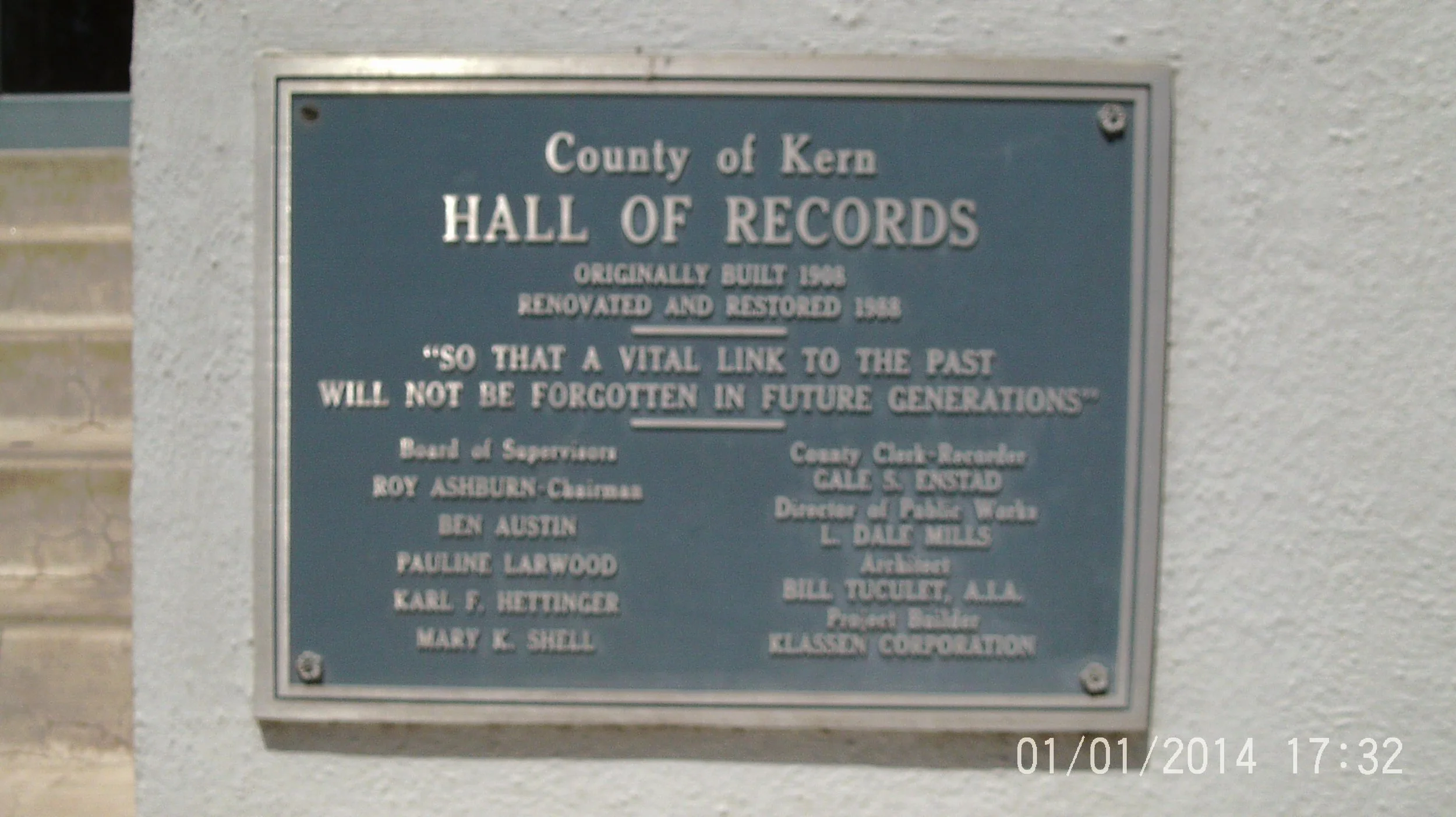
Bakersfield Hall of Records
March 2014
BakersField, CA
condition assessment and repair recommendation for 100+ Year Building

Overview

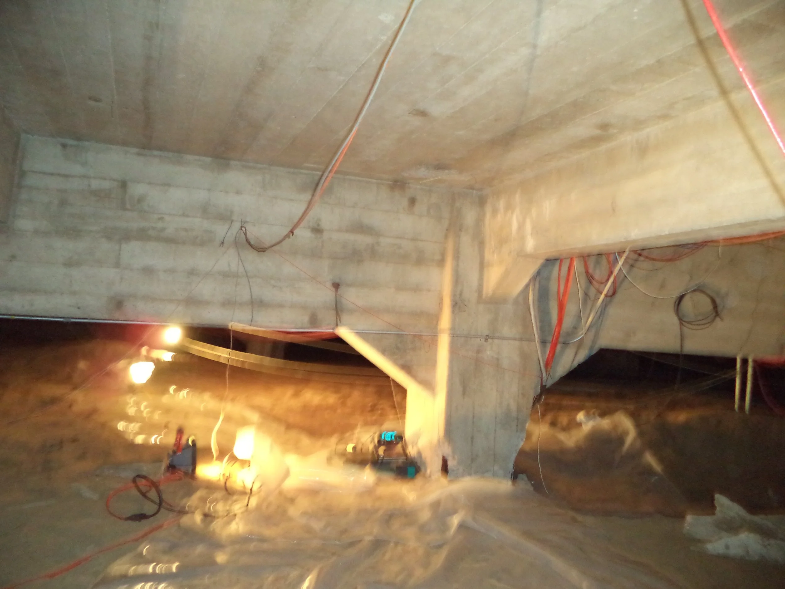
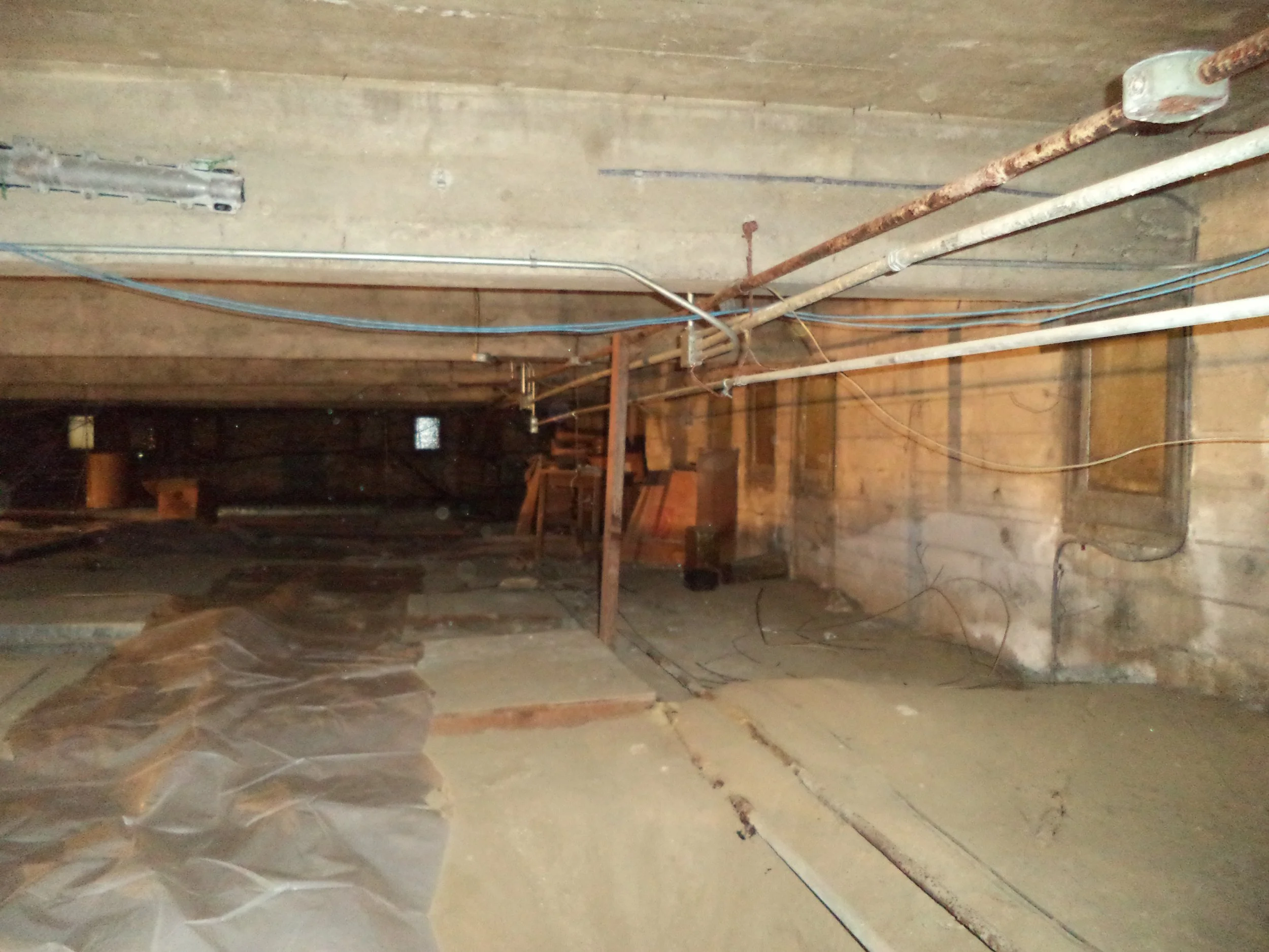
The Hall of Records building, located in Bakersfield, CA, is a structure originally built in 1908. It underwent renovation in 1988. Over time, the building has experienced extensive reinforcement corrosion and concrete spalling, particularly in its foundation columns and beams located in the basement and crawl space. Exterior walls, in contrast, showed minimal deterioration during initial evaluations. The significant damage observed prompted evaluations to determine the internal condition of the concrete members.
Concrete Science, Inc. was contracted to perform various tests and evaluations, including non-destructive methods like pulse velocity and acoustic impact-echo tests, laboratory analysis of concrete cores and powder samples, and soil testing. The objective was to understand the cause and extent of this deterioration and inform potential repair options. Additional testing was later performed on the exterior sides of the building to further assess conditions there.
SCOPE OF WORK
The evaluation involved a multi-faceted approach combining field testing and laboratory analysis.
-
Pulse velocity and acoustic impact-echo tests were conducted on accessible walls, columns, and beams in the basement and crawl space to assess internal concrete condition.
-
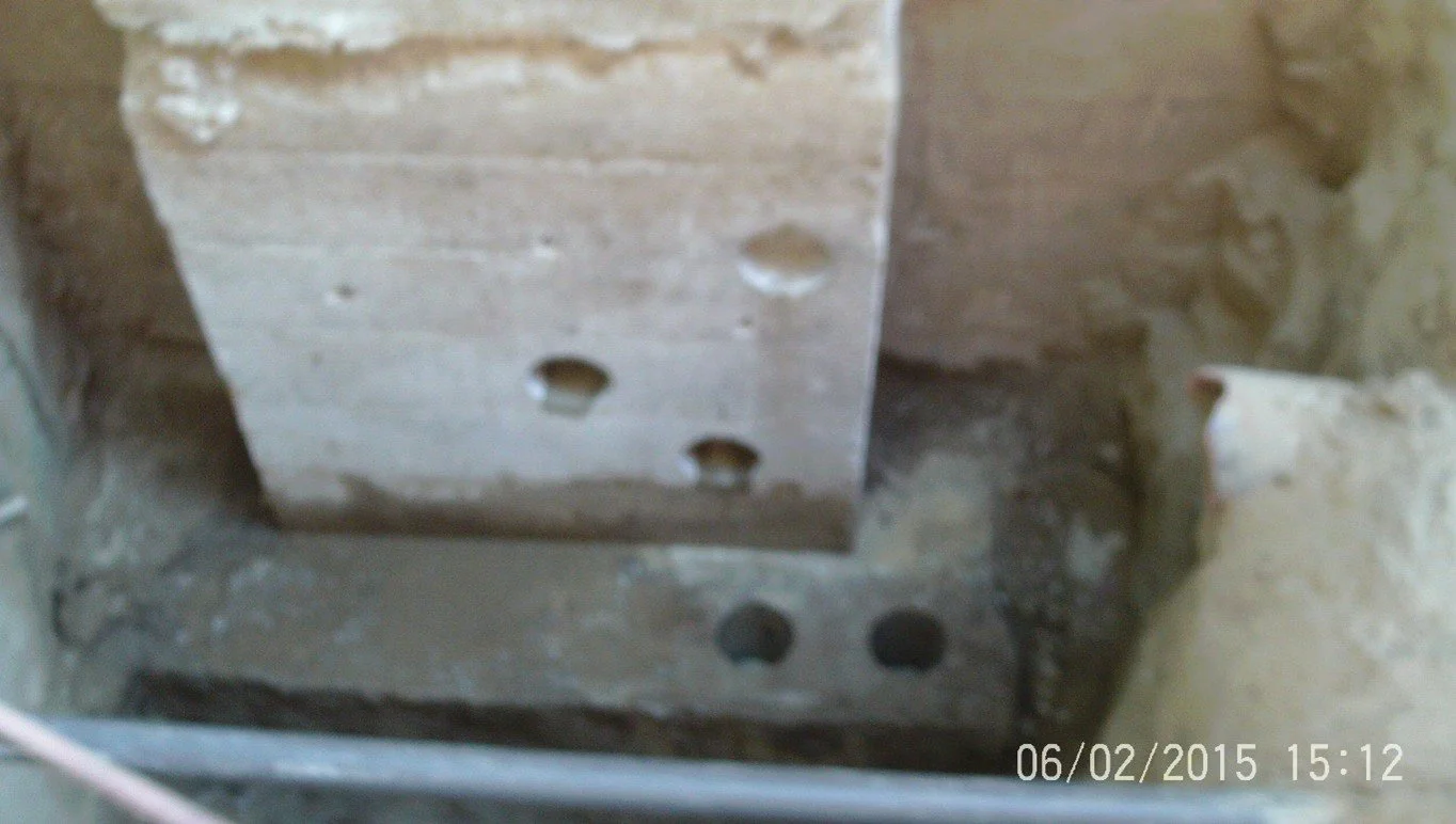
Specific columns, beams, and footings, including some showing visible distress and others without, were selected for in-depth testing. Three column footings (F5, G5, K6) were exposed. Two exterior column locations (north side and southeast corner) were later selected for additional testing.
-
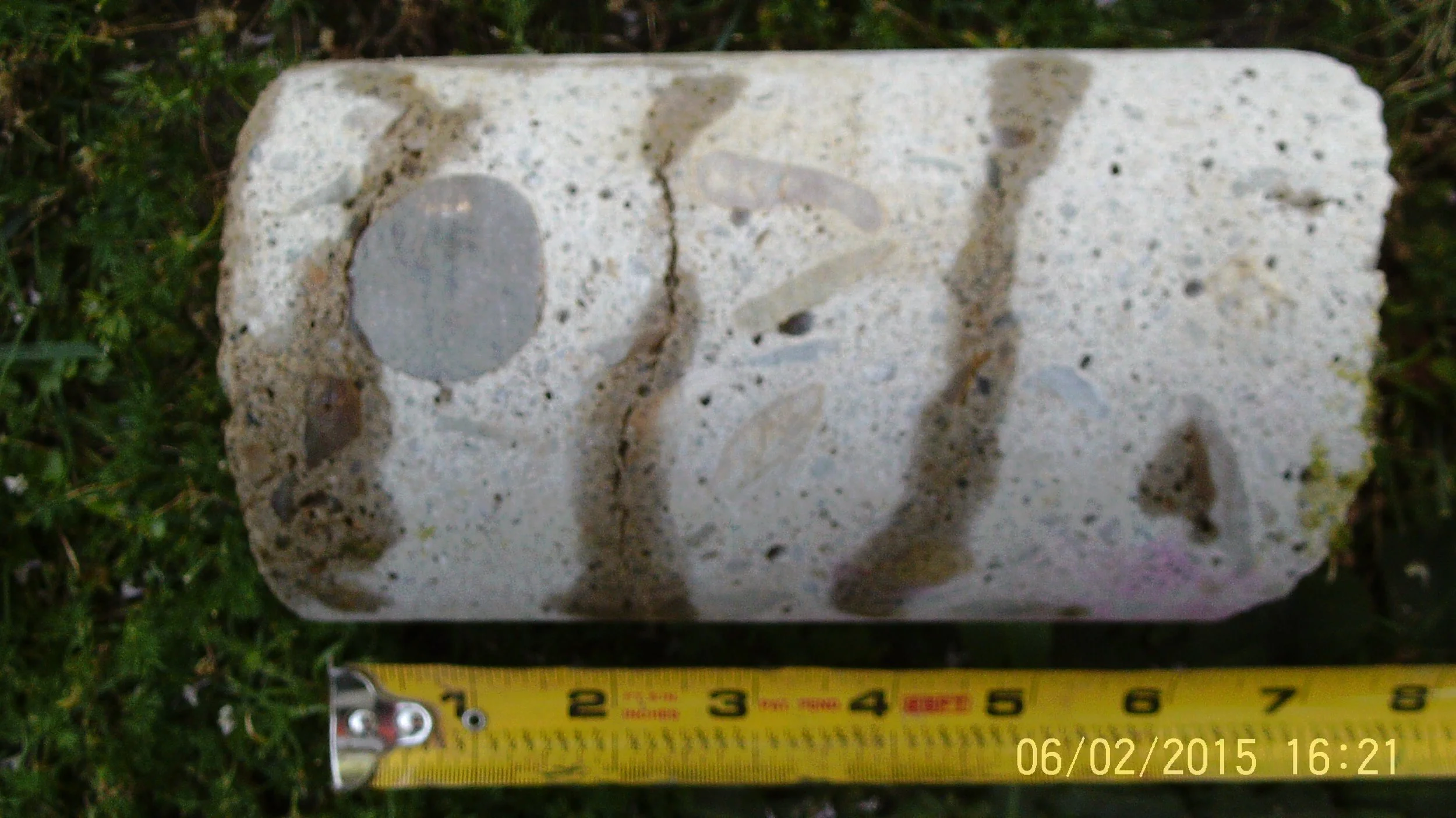
A total of 32 cores were drilled from various interior columns, beams, and footings. Additional cores were provided by another laboratory. Five cores were later removed from the north side exterior column/footing and four from the southeast corner exterior column/footing. Powder samples were obtained from concrete members for chemical analysis, and soil samples were collected from locations adjacent to columns and footings for testing. Reinforcement was exposed via partial cores at selected locations.
-
This included Schmidt Hammer testing on various members to estimate concrete compressive strength. Half-cell electrical corrosion potential tests were conducted on exposed reinforcement at selected locations to determine corrosion activity.
-
Concrete core samples were tested for compressive strength. Powder samples were analyzed for acid soluble chloride content, pH, and carbonation depth. Five concrete cores were microscopically analyzed for internal deterioration. Soil samples were tested for pH, resistivity, chloride content, and sulfate content.
-
Field and laboratory data were analyzed and presented in written reports detailing findings and conceptual repair options.
KEY FINDINGS
The evaluations revealed significant concrete deterioration and identified several contributing factors:
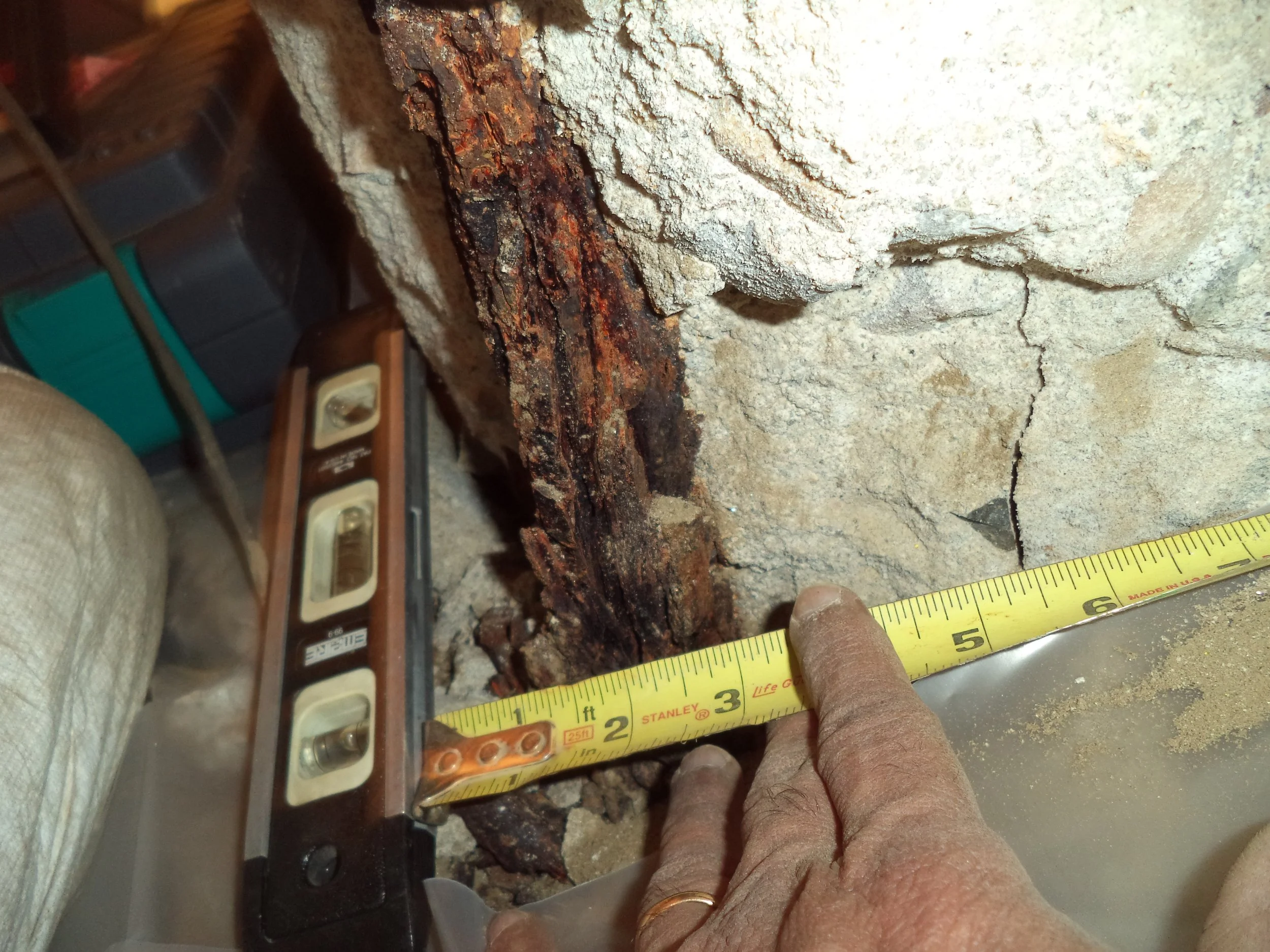
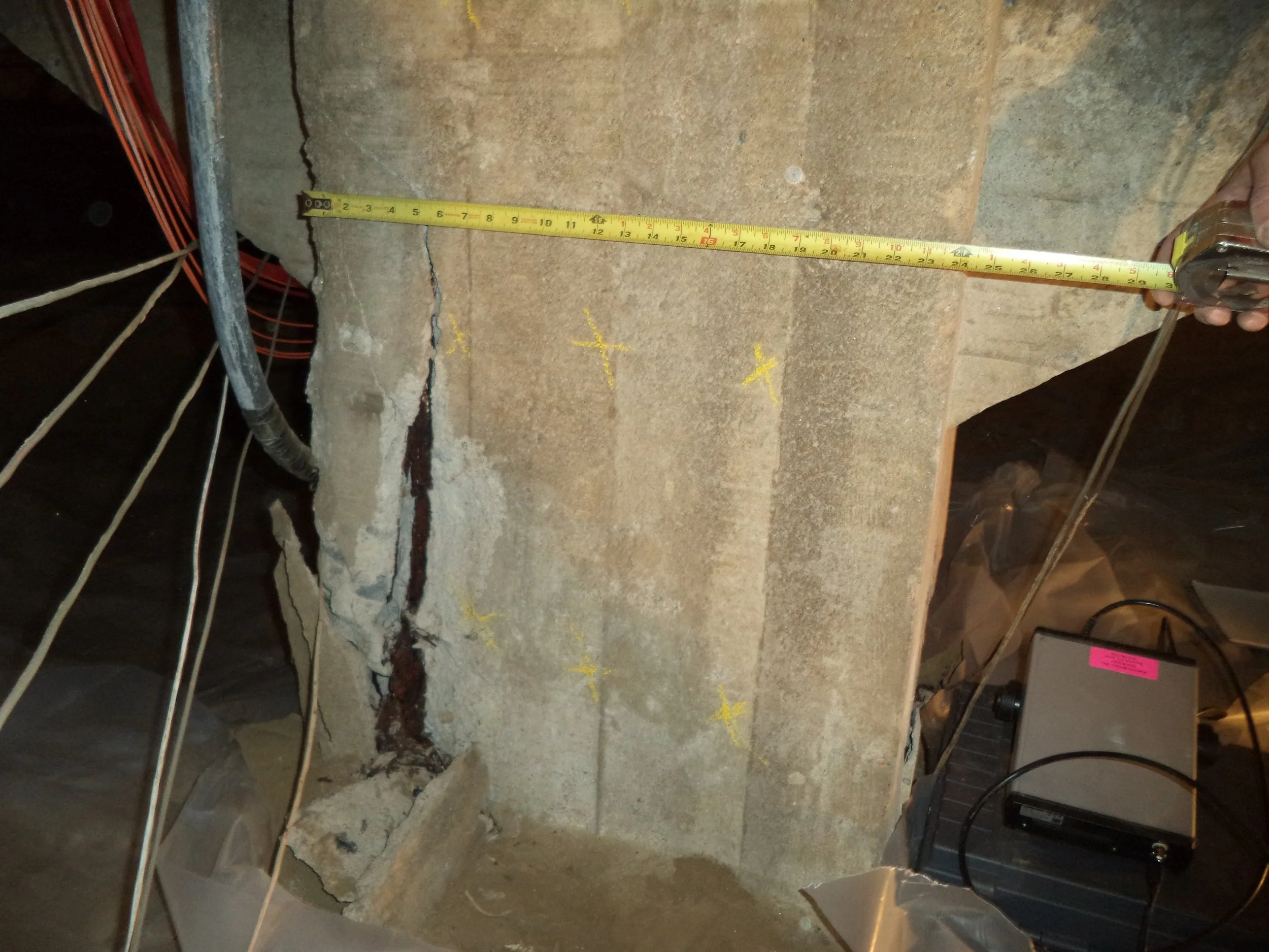
1. Visual Damage:
Significant spalling and exposed, corroded reinforcement in basement columns and beams
Exterior walls and elements showed minimal deterioration
2. Non-Destructive Testing Results:
Pulse velocity ranged from 9,000 to 12,000 ft/s, indicating variable quality
Impact-echo results showed wide frequency variations and localized delamination
No major internal flaws detected in majority of tested members
Concrete Strength:
Estimated strength from Schmidt Hammer:
Columns: ~2,900 psi
Beams: ~2,800 psi
Walls: ~3,100 psi
Slab: ~4,200 psi
Core-tested strength:
Columns: ~2,750 psi
Beams: ~2,880 psi
Footings: ~4,390 psi
Walls: ~3,140 psi
Exterior cores: 2,400 to 4,290 psi
Corrosion Activity:
Half-cell readings at Column F5 indicated active corrosion (-364 mV)
Other locations showed low probability of corrosion
Reinforcement in exterior columns appeared minimally affected
Chloride Content:
Ranged from 0.07 to 16 lb/cu yd
Most severe corrosion correlated with highest chloride content (e.g., Column F5: 14.8 lb/cu yd)
Levels above corrosion threshold (1.5 lb/cu yd) were common in beams and columns
Exterior concrete had lower chloride content (0.20 to 0.84 lb/cu yd)
Carbonation:
Surface carbonation depths exceeded clear cover in exposed members
pH dropped to 9.5 in carbonated zones
Footings showed ~1-inch carbonation depth
Exterior columns showed no carbonation effects
Sulfate Attack:
Petrography confirmed gypsum-related deterioration in footings F5 and K6
Localized weakening and sub-horizontal fractures observed, especially in F5
Columns appeared porous but not chemically degraded
Soil Conditions:
Soils classified as corrosive to severely corrosive
High chloride and sulfate concentrations detected
Southeast exterior column site had moderately corrosive soil (resistivity 5100 ohm-cm)
Additional Observations:
One exterior column showed internal vertical cracking despite no external signs


RECOMMENDATIONS & SOLUTIONS
-
Estimated extension to the service life: 10+ years
Remove spalled concrete to a depth of at least 6-inches.
Remove and replace corroded reinforcement.
Install galvanic anodes to protect the steel from further corrosion.
Rebuild the columns to specified dimensions using either high quality shotcrete or cast-in-place concrete made with Type V cement or Type II cement with type F fly ash.
Apply two coats of high quality elastomeric paint on all footings, columns, beams, walls, and underside of the 1st floor slab.
Install isolation material such as 2 layers of thick polyethylene sheeting between the soil and the foundation system.
-
Estimated extension to the service life: 20+ years
Remove spalled concrete to a depth of at least 6-inches.
Remove and replace corroded reinforcement.
Install galvanic anodes to protect the steel from further corrosion.
Rebuild the columns to specified dimensions using either high quality shotcrete or cast-in-place concrete made with Type V cement or Type II cement with type F fly ash.
Apply two coats of epoxy on footings, columns, beams, walls, and underside of the 1st floor slab.
Install isolation material such as 2 layers of thick polyethylene sheeting between the soil and the foundation system.
-
Estimated extension to the service life: 30+ years
This repair will not only protect the foundation from corrosive soil, but the use of carbon fiber will strengthen the columns and column-beam connection to resist higher building and seismic loads.
Remove spalled concrete to a depth of at least 6-inches.
Remove and replace corroded reinforcement.
Install galvanic anodes to protect the steel from further corrosion.
Rebuild the columns to specified dimensions using either high quality shotcrete or cast-in-place concrete made with Type V cement or Type II cement with type F fly ash.
Install carbon fiber with epoxy resin over footings, columns, beams.
Apply two coats of epoxy on the underside of the 1st floor slab and walls.
Install isolation material such as 2 layers of thick polyethylene sheeting between the soil and the foundation system.
-
Estimated extension to the service life: 30+ years
This repair option uses impressed current cathodic protection system which is typically used in bridges and highway structures. The impressed current cathodic protection system is essentially installing an anode mesh over the entire footing, column, beams and the underside of the slab. The mesh needs a thin layer of shotcrete to embed it and then an electrical current is provided using an external rectifier to the entire structure to protect it from further corrosion. The system needs periodic checkup and maintenance.
Remove spalled concrete to a depth of at least 6-inches.
Remove and replace corroded reinforcement.
Rebuild the columns to specified dimensions using either high quality shotcrete or cast-in-place concrete made with Type V cement or Type II cement with type F fly ash.
Install impressed current cathodic protection system.
Install isolation material such as 2 layers of thick polyethylene sheeting between the soil and the foundation system.
-
Estimated extension to the service life: 50+ years
Remove & Replace complete foundation system with high quality and low permeability reinforced concrete using Type V cement or Type II cement with type F fly ash.
Remove corrosive soil in contact with new foundation or install isolation material such as 2 layers of thick polyethylene sheeting between the soil and the foundation system.
Repair Goals:
Reestablish structural support
Prevent further corrosion from aggressive soil
Minimize moisture and chemical ingress
Conceptual Repair Options:
Remove spalled concrete and rusted rebar; replace rebar; add galvanic anodes; rebuild with high-quality concrete; apply elastomeric paint; isolate soil with sheeting
Same as Option 1 but use epoxy coating instead of paint
Add FRP (carbon fiber) reinforcement over footings, columns, and beams; apply epoxy coating; soil isolation sheeting; estimated 30+ year service life (Recommended)
Install impressed current cathodic protection system embedded in shotcrete; includes full concrete and rebar repair; requires periodic maintenance; 30+ year service life
Completely replace foundation system with Type V/Type II concrete and either remove soil or add barrier; estimated 50+ year service life
Preferred Option:
Option 3 was recommended for both interior and exterior columns and footings
Target cracked members for FRP strengthening
Exterior FRP wraps should extend at least 12 inches above grade and be finished with coating/paint
If budget constraints limit full application, prioritize structurally important wall segments and accessible exterior columns
Monitoring Recommendations:
If Option 3 not implemented fully, conduct structural inspections every 5 years or after major seismic events
THE OUTCOME
The investigation concluded that severe concrete deterioration was driven by chloride ingress, carbonation-induced pH loss, and sulfate-laden soils. These factors resulted in reinforcement corrosion and localized footing failure. FRP-based repair, particularly Option 3, was recommended to restore integrity, extend service life, and reduce future maintenance. Whether these repairs were executed is not specified in the source documentation.
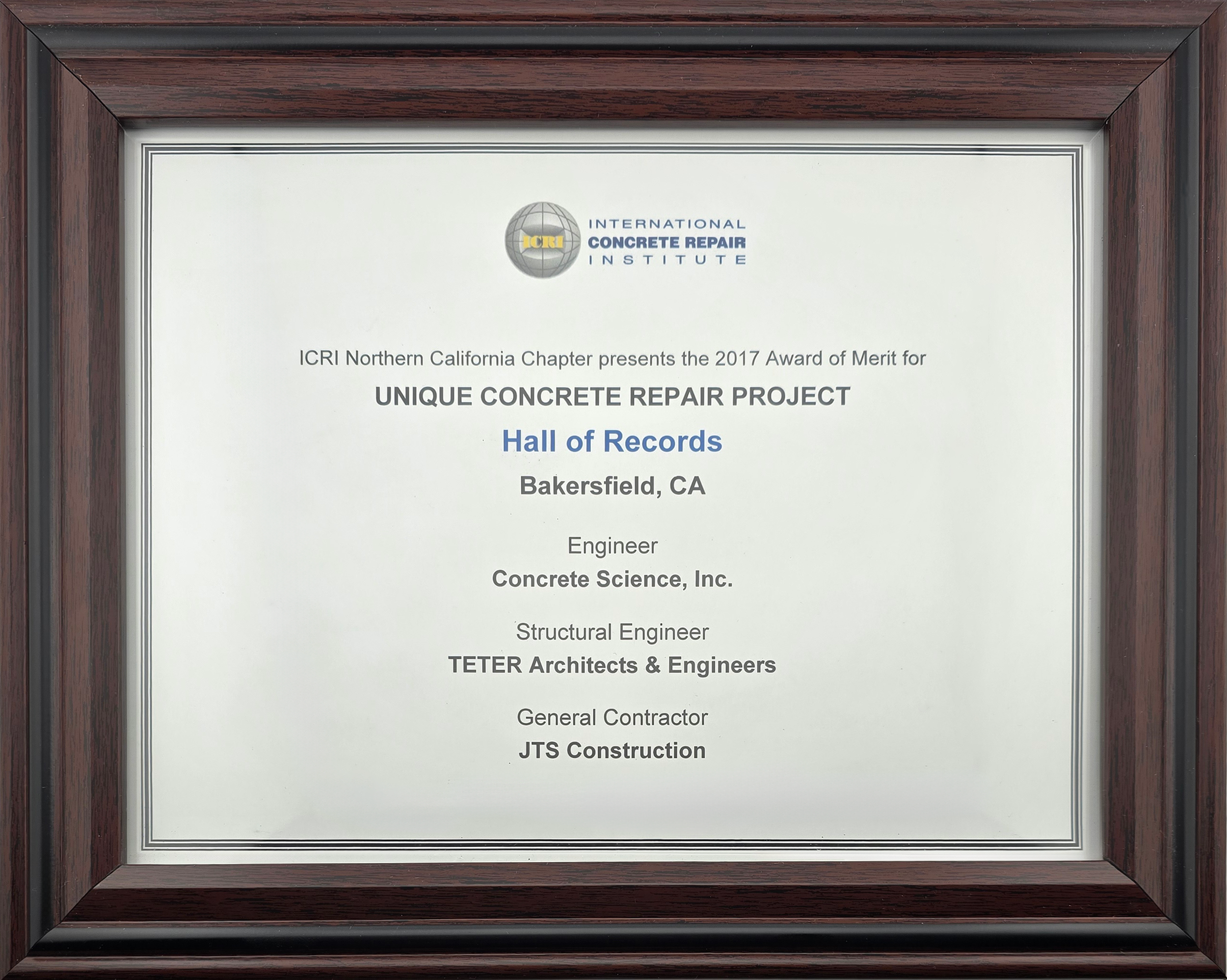
Thank you to our partners
General Contractor
Structural Engineer